Reading serial data stream from an ADC


Recently I wanted to draw some discharge curves of old LiPo cells from old laptops, to find which were still serviceable.
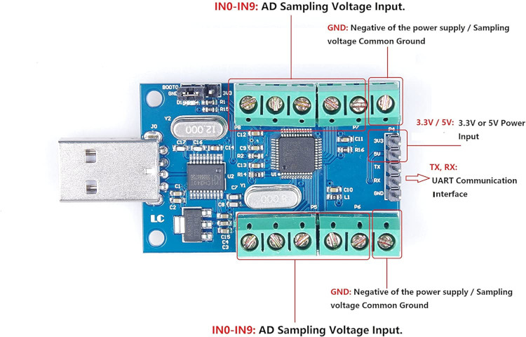
You can buy on the internet, for about 6 GB pounds including postage, a 10 channel ADC ( Analog to Digital Converter) that plugs into a USB port and streams ten channels to 10 bit accuracy twice a second. It appears as a com port to a PC.
It sends its values both as a raw number between 0 and 4095, and converted to a voltage.
It is dead easy to test- just plug in and run a serial terminal set to 115200 baud. It is also easy to use the data to create a stored file for later analysis, or real-time display. The limit is you get data updates only two times per second, and you need to be careful not to allow inputs out of the range 0 to 3V3.
Analog input channels: 10 channels single-ended input;
Sampling input voltage range: 0-3.3V;
Power supply voltage: 3.3V / 5.0V;
Resolution: 12 Bit;
This is a very easy-to-use device. Simply plug the device into a computer's USB port, and it implements a serial communication port connected to a device that continually sends data that describes the voltages present on its ten input channels. This data is sent at 115200 baud rate. The serial port (or the program that you use to read data from this serial port) will probably need this rate information to correctly receive data.
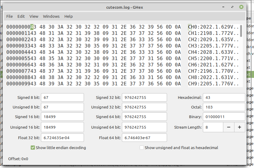
A hex viewer makes it easy to see the data format...

The data format then something like this, where tab is chr$( 9):
CH0:2010 tab 1.620V CRLF . . . . ie Channel 0, reading 2010 out of 4095, ie 1.620V
CH1:2187 tab 1.761V CRLF
CH2:2013 tab 1.621V CRLF
CH3:2192 tab 1.766V CRLF
CH4:2014 tab 1.622V CRLF
CH5:2187 tab 1.761V CRLF
CH6:2006 tab 1.615V CRLF
CH7:2178 tab 1.753V CRLF
CH8:2003 tab 1.612V CRLF
CH9:2181 tab 1.757V CRLF CRLF
This 11-line sequence is repeated two times a second. This data frame is finished by the TWO CR/LF ( chr$( 13) +chr$( 10)) pairs.
The maximum raw value (4095 decimal) corresponds to 3.3 volts.
Because the asynchronous serial interface is so common and well understood, it would be a challenge to find a computer that cannot readily use this device. If you want to monitor 25 voltage signals, buy three devices (and a USB hub, if necessary.)
There are some limitations. Many applications need more than two samples per second, and therefore must use some other device. There is no bipolar measurement capability and no multiple range facility. Level-shifting and divider circuits outside the analog-to-digital converter might handle simple cases at very low cost, but more capable (and expensive) devices would be more flexible and not require design and fabrication effort.
Inputs larger than 3.3 volts or less than zero volts are likely to damage the device. There is no over voltage nor negative input protection.
In the past all my serial devices were 'send on request', ie you send a query or command and get back a packet of defined format. Here, the problem is detecting the whole frame and parsing out the bits I want. Various schemes worked, but at times I got incomplete frames and dropped a value.
I think the best solution came when I realised that rather than regarding the double CRLF pair as the END of message, I could think of it as the START of a new frame, and read the whole data section knowing it is ten channel sections each 17 bytes long...
I also had the problem that I normally run LB on Linux machines, and had never got it to read their serial ports, so I had to turn to my one remaining MS machine. ( Terminal programs allowed me to see the datastream, but not LB. Editing the registry so 'Com1' points to '/dev/ttyUSB0' didn't work for me....) Then I managed to get it to work with LB/Wine/Linux!!
    open "COM33:115200,n,7,1" for random as #fIn

    CRLF2$  =chr$( 13) +chr$( 10) +chr$( 13) +chr$( 10)

    I$      =input$( #fIn, lof( #fIn))   ' discard anything in buffer

    timer 1000, [o]

    wait

  [o]
    print "Checking ADC",
    cnt =0

    do
        i$      =input$( #fIn, 1)   '  read single byte.
        if i$   =chr$( 13) or i$ =chr$( 10) then cnt =cnt +1 else cnt =0
    loop until cnt =4   '   we've met the frame separator...

    I$ =""
    do
        i$  =input$( #fIn, lof( #fIn))
        I$  =I$ +i$
    loop until len( I$) >=10 *17    '   pick up the whole frame.

    'print I$   '   print all ten channels every second OR a selected one.
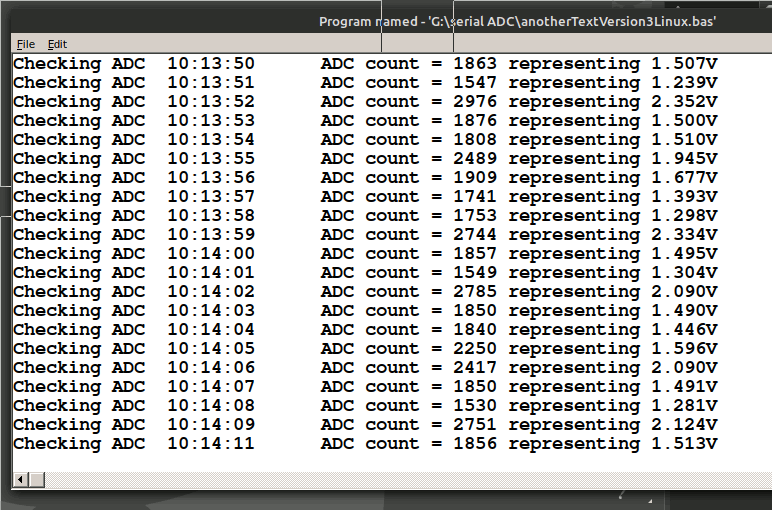
    print time$(), "ADC count = "; mid$( I$, 17 *5 +5, 4); " representing "; mid$( I$, 17 *5 +10, 6)

    wait
CH0:2193	1.726V
CH1:1999	1.581V
CH2:2123	1.716V
CH3:1979	1.578V
CH4:2137	1.728V
CH5:2524	2.031V
CH6:2169	1.747V
CH7:2010	1.619V
CH8:2190	1.765V
CH9:2034	1.642V

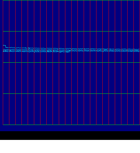
This is a GOOD LiPo cell discharging. The trace starts again at the left so really represents 5 screen-widths of data. The initial dip was when I connected the load, and shows the internal esistance is low. The slow down trend shows the capacity is still a sizeable fraction of the initial cell rating.
Note that by rem-ing or de-rem-ing you can save all or some data to file, to a graphic window, or as text dump...

    'nomainwin

    WindowWidth  =540
    WindowHeight =480

    open "COM33:115200,n,7,1" for input as #fIn

    CRLF2$  =chr$( 13) +chr$( 10) +chr$( 13) +chr$( 10)

    open "ADCdata.txt" for output as #fOut

    open "ADC read from serial USB" for graphics_nsb as #wg

    #wg "trapclose quit"

    #wg "fill darkblue ; color green"
    #wg "up ; goto 10 430 ; down ; goto 510 430"
    #wg "up ; goto 10 365 ; down ; goto 510 365"
    #wg "up ; goto 10 300 ; down ; goto 510 300"
    #wg "up ; goto 10 235 ; down ; goto 510 235"
    #wg "up ; goto 10 170 ; down ; goto 510 170"
    #wg "up ; goto 10 105 ; down ; goto 510 105"
    #wg "up ; goto 10  40 ; down ; goto 510  40"

    #wg "color cyan ; flush"

    I$      =input$( #fIn, lof( #fIn))   ' discard anything in buffer

    timer 100, [o]

    e =0

    wait

  [o]
    timer 0

    if e =0 then #wg "up ; goto 10 430 ; down"

    cnt =0

    do
        b$      =input$( #fIn, 1)   '  read single byte.
        if b$   =chr$( 13) or b$ =chr$( 10) then cnt =cnt +1 else cnt =0
    loop until cnt =4   '   we've met the frame separator...

    I$ =""
    do
        d$  =input$( #fIn, lof( #fIn))
        I$  =I$ +d$
    loop until len( I$) >=10 *17    '   pick up the whole frame.

    'print "Checking ADC",
    'print I$   '   print all ten channels every second OR a selected one.
    'print time$(), "ADC count = "; mid$( I$, 17 *5 +5, 4); " representing "; mid$( I$, 17 *5 +10, 6)
    #fOut  I$
    yScreen =430 -val( mid$( I$, 17 *5 +5, 4)) /4096 *400
    if ( e mod 20) =0 then
        #wg "color red ; line "; 10 +e; " 430 "; 10 +e; " 30"
        #wg "color cyan"
        #wg "up ; goto "; 10 +e; " "; int( yScreen )
        #wg "down"
    end if

    #wg "goto "; 10 +e; " "; int( yScreen)
    e   =( e +1) mod 500

    timer 100, [o]

    wait

    sub quit h$
        #wg "getbmp scr 1 1 450 520"
        bmpsave "scr", "ADC-trace.bmp"
        timer 0
        close #fIn
        close #wg
        close #fOut
        end
    end sub