Later I came across the marvellous machines such as eggbots, flag-wavers, and circular-coordinate ( r, theta) sand-tables. Thanks this time to Brian Shapiro I've made quite a few eggbots now from cannibalised stepper motors, and usually using Bruce Shapiro's EiBotBoard from SparkFun.
I had also come across a two-cable suspension scanner thirty-plus years ago, which moved a photocell across a slide-projector image to digitise it! It could also scan a microphone with AtoD across a sound field, etc. Of course nowadays we have digital 2D sensors available in cameras et al. This became popular again more recently, since it is easy to MAKE, 'tho the transfoming of coordinates has some overhead when programming, and scales easily to large sizes where you might want to 2D-position not a pen, but instead a plasma torch or laser burner! See some lovely work by Chris
 -
-
After starting playing with this kind of non-Cartesian-coordinate plotter, I found Chris's version online. It also addresses the problem with eggbots when you want to drive a vector-addressed and -controlled machine to represent 2D-brightness-coded images. You can raster-scan most machines, but it is impossible to make pen-size change mid-plot, so the basic image has to be two-tone. I'd previously played with Rasterbator-style images, which code brightness via dot-size.
One way round this is to turn the greyscale image into a single path, where the line spacing has been altered to represent brightness. This is hairy, mathematically, involving the travelling-salesman problem in visiting all the necessary points.
See Evil Mad Science
Chris's version instead raster-scans an image, & deflects at each pixel for a 'blip' of length proportional to brightness. I've now implemented a similar scheme in Liberty BASIC. ( I tend tp program in Python on a Pi at present, but it is SO much harder to knock up GUI front-ends in Python.)
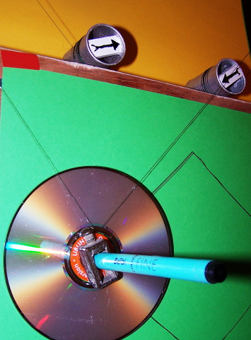
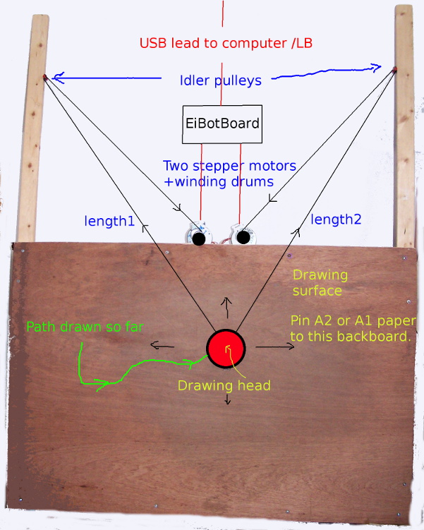
The LB program at present shows the two suspension cables as circles centred at the two suspension points. Their intersection is where the pen will go. It accepts SVG files, so I simply draw a desired shape as a continuous sequence of straight line segments in Inkscape and save as a SVG, or use a LB program already written to generate the path mathemagically.
The motors and board are presently waiting to be given a rather more pemanent form than the lash-up indicated here! Incidentally I wonder if anyone else has a junk box that has wooden cotton reels in it as well as old 35mm plastic film cannisters!
It's great fun to play with 'mechanotronic' combinations of computer and electrical motors, etc. To a retiree that counts as 'useful'.
Like many of my projects, this one is open-ended. I'll certainly add file selectors, and use ImageMagick programmatically to convert ANY chosen image to a BMP of the correct size, and do some range-setting/scaling on the SVG file to ensure it does not go out of bounds.. Source and a test SVG file here