Interfacing with UBW devices and JB/LB
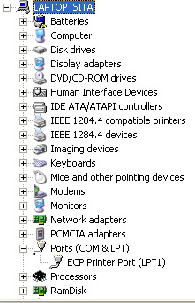
This was a laptop with a parallel port ( LPT1) and no serial ports.
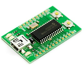
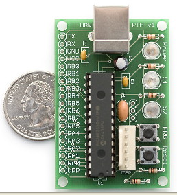
SO.... Buy a UBW ( about 25 dollars from SparkFun. They sell three versions. One is a kit to build yourself. and connect it with a USB lead to your computer. From here on it APPEARS to the computer as a new COM port.
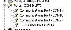
You can 'talk' to the UBW from any terminal program, and Liberty & Just Basics know how to talk to a serial port UBW- you issue a one-line command to OPEN the port. You can then PRINT to the port for outputting, and input from it. The different versions have different total numbers of pins available, so the BASIC code may need changing to refer to port A or B or C. You can locate which COM port it is programmatically, but the easiest is via Control Panel as described above- look for a new COM number! In the picture, on another computer, there were already two hardware serial ports, COM1 & COM2. COM10 is the UBW I'd just plugged on.
The UBW accepts one-line commands sent as 'ASCII strings'. Send string '0,0,0,0' ( this is letter 'O' comma zero comma zero comma zero) and 24 pins all are set low ( zero volts approx.) The 'O' ( as in 'O' for 'Orange') meant an 'O'utput was being specified, and decimal 0 ( number 'zero') means binary 0000 0000 is to be sent to each of 3 'ports' A, B and C.
Send instead 'O,0,0,2' and you are 'O'utputting zeroes again to all pins EXCEPT pin C1. This is because 2 in decimal is 0000 0010 in binary, and this pin is referred to as pin C1, since we call the pins from C0 to C7. Pin C1 however is set high.
Just one complication. Before the above, you needed to send a command string 'C,0,0,255'. The decimal 255 is binary 1111 1111 and says ''C'onfigure all C's pins are to be outputs'. The two zeroes say 'port A & port B are to each have 8 input pins'. And when the program finishes you should close the UBW port.
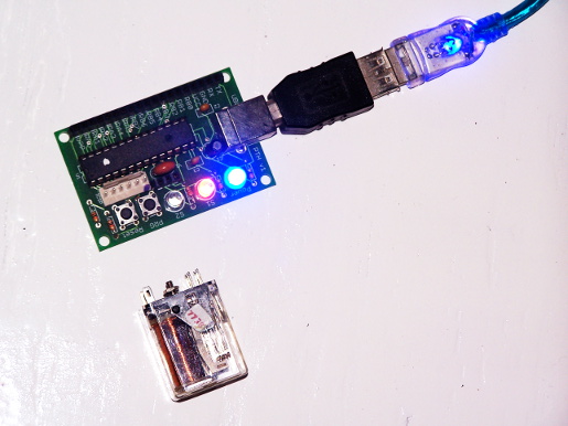
Commands are case-insensitive, and can be followed by CR, CRLF or LF (effectively, 'Return'). With code like the following you can see the pin go high and low again after one second, because the board has a built-in LED on the controlled pin.
    nomainwin

    '   For me, UBW is COM10. Look in Device Manager via Control Panel.
    '   Change as necessary- it is NOT COM1 or 2 which are internal ports.
    open "COM10: 9600, 8, N, 1, RS, DS0, CS0" for random as #UBW

    '   Setting direction registers to PortA in (decimal 255, binary 1111 1111)
    '   and Ports B & C out ( decimal 0, binary 0000 0000).
    #UBW "C,255,0,0"

    '   Writing out new bit states  0    0    2 so Port C1 red LED lights.
    '   C1 means the SECOND least significant bit, since we count 0 to 7 for an 8-bit byte.
    '   Note first character of command string is alpha 'o' not decimal '0'.
    '   The command means output decimal 2 ( binary 0000 0010) on port C; decimal 0 ( 0000 0000) on ports A and B.
    #UBW "O,0,0,2"

    '   Wait one second.
    timer 1000, [MoveOn]
    wait
  [MoveOn]
    timer 0

    '   Writing out new bit states  0    0    0 so Port C1 red LED extinguishes.
    '   This time, output 0 ( 0000 0000) to all three ports.
    #UBW "O,0,0,0"

    close #UBW

    end
You might also like to look at Brian Schmalz's Tutorial and command documentation.
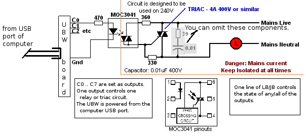
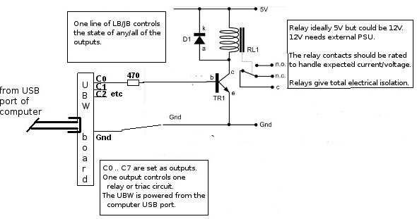
To control mains voltages and large currents, you'd use a circuit like the following. It is optically isolated (mains and computer electronics voltages do not co-exiist happily...) I use eight of these to drive kilowatt light bars disco-fashion. You can switch as fast as the mains (50 or 60Hz) if you want.