PiscoLitez- An 8-light DiscoLitez rig controlled by Python on the Pi
(I'm a fan of Chilean pisco)
This is about a bar of mains lamps controlled from your Raspberry Pi's GPIO pins. It gave me a chance to get my computer interacting with the real world & humans in an impressive way. (I WAS a teacher of IT...) The bar of lights was originally made for control via DiscoLitez, the Winamp add-on, and then was used for several years with Liberty BASIC. Now dusted off for use on my Pi! I do come from the home of Bridgwater & Taunton carnivals!
NB You need old-fashioned filament lights if you want to flash them. CFL lights do NOT like this kind of use, and I'm wary of trying mains LED lights. For a more eco-friendly set-up, use high-efficiency LEDs & low voltage high current supplies, and use appropriate current-rated wiring.

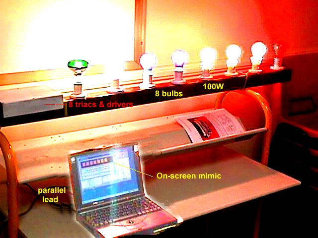
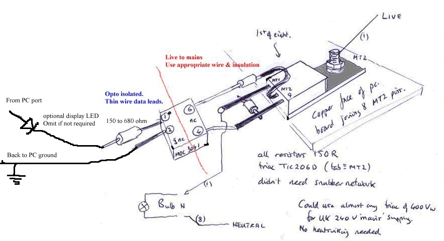
The photos give an idea of my particular construction scheme- the bar has 8 x 100W bulbs, is about 1.5m long ( 4 feet), and has the interface drive box at the end. Cables are to Pi's ground and GPIO pins & to mains. Eight identical zero-crossing opto-isolators drive triacs with no mains interference. The bulbs tend to be the most expensive bit if you get carried away- each channel could drive 1kW of bulbs.


Note if using positive logic, the 3.3V 'true'/ 'high' outputs will NOT drive an LED in series with the optoisolator. Use just the limiting resistor. Alternatively, use logic 'low' as a command to turn on the triac, wiring it from the +5V line to the chosen GPIO pin.
BEWARE MANY COMPONENTS ARE AT MAINS POTENTIAL!
Use proper insulation/earthing practice. Track spacing on strip board is NOT designed to insulate mains voltage- hence my 'mid-air jungle' layout. Use earthed boxes or double-insulation, and use rubber grommets and sound cable termination. The PI is separated from the mains section by insulation good for 10000V in the opto-isolators, and the series resistor limits the current draw. Turning a pin ON delivers the 'high' 3.3V, and if you are using LED displays this makes logical sense.
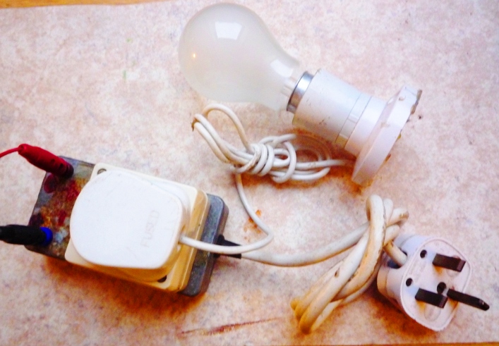
I have the whole 8-channel set-up available, but for testing use just a single opto-isolated triac & 100W bulb. kilowatts of bulbs create kilowatts of heat- not sensible in small computer 'dens'.
 -
- 
I did not find I needed the 'snubber' or RC network across the circuit...
You can write Python, C, bash... programs to sequence & time the lights, etc. You will need the GPIO library installed. If you send appropriate patterns and wave the bar of lights through the air you can 'write in mid-air'- think of it as an ink-jet printer sending flashes of colour!!
The following python code was adapted from MagPi Issue 2 examples which were unfortunately published with wrong indenting.
#!/usr/bin/python

import time
import RPi.GPIO as GPIO

GPIO.setup( 11, GPIO.IN)
GPIO.setup( 12, GPIO.OUT)

while True:
    if GPIO.input( 11):
        GPIO.output( 12, True)
    else:
        GPIO.output( 12, False)
    time.sleep( 0.2)
It is sensible to experiment at first with cheap LEDs & resistors on the GPIO port.
Hope you are encouraged to experiment!
Please contact me with queries or adaptations at mr.john.f@gmail.com